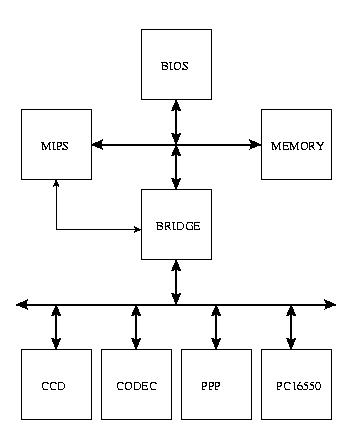
Version 1.2 of the DIGCAM is designed with a two level bus structure. The bus structure is designed as follows:
Main System Bus
Peripheral Bus
In an effort to increase the speed at which the DIGCAM operates, we added a peripheral write buffer to the BRIDGE such that the MIPS would not be blocked while a peripheral write completes. There are three configurations of the bridge with 0, 1, and 2 words write buffers respectively.
Core source codes and synthesis scripts:
Scripts for analyzing and synthesizing design:
Scripts used for power analysis:
Core source codes and synthesis scripts:
Scripts for analyzing and synthesizing design:
Scripts used for power analysis: